
CI-V based remote antenna switch
Block diagram description

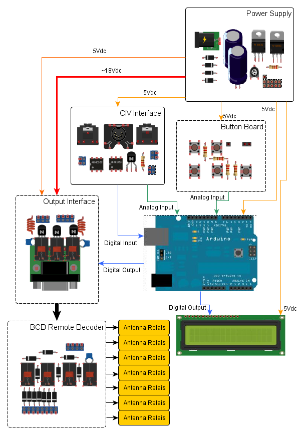
The switch has been build using several little modules, each performing a specified task, linked together: of course
even if this approach seems less "professional" than creating a single "big" printed circuit, it's for sure simpler
to build and to test and fits perfectly with the "KISS" filosophy I've adopted for this project.
Moreover, I used a recycled boxes for both the control box and the remote unit: using little modules allowed
me to fit them within the box with a little effort.
The remote unit is really simple and it's nearly identical to several others described on the net. It only differs for the way of feeding antenna relays: it uses only 4 wires to drive 7 relays. Most Internet projects use a wire for each relay (plus a GND of course): I went for just 4 wires because:
- I already have a remote antenna swicth (4 position) connected to my "patch panel" using an XR connector (used to quickly disconnect all cables when storms arrive)
- More important: I should minimize I/O pins used in Arduino
Looking at the diagram, you'll for sure note that I used lots of relays: lines going from control unit to remote box are feeded via relays as well as the BCD converter which is completely "mechanic". In my humble opinion, this is the best way to both avoid RF going back to the control unit and keep the construction simple. Of course, it presents more "points of failure" since a single relays failure could block the entire system. Also you can easily substitute the relays with electronic devices (BJT and a simple BCD to decimal converter like 74LS42 or 74HC42, providing you properly traslate input signal to TTL levels).
READ CAREFULLY: This project (especially the electronic parts) is not intended to be a "ready-to-use" device but as a sort of plot that can be used to deploy your own device. Many choices have been made accordingly to my own personal needs and thus I'm almost sure they won't fit other environments. In other world, before starting the work, I suggest you review the whole project (with a closer look at the electronic part) to verify it really suite yuor needs.
Here a brief description of single blocks
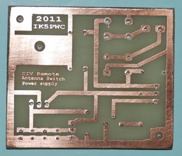
Power Supply

The power supply is able to handle two different voltage levels:
- 5 volt to power the logical devices within the control box
- A variable voltage to power relays
Since antenna relays are used ones, often with different requirements, I ended up building a modula power supply which can configured "on the field" to properly supply those relays.
The power supply uses another little power supply as input instead of a common transofmer (of course, you can use a simple transformer and a rectifier bridge if you need): again, this design has been driven exclusively on my needs since in my drawers I've found lots of little switching power supply (coming mainly from computer peripherals). Those devices are often quite adeguate for ham use, but I added a small rectifier and a stabilizer, since I noted that often those devices are quite "noisy" from the RF point of view.
The power supply printed circuit has many sockets as the number of board to power.
Keyboard
The Control unit uses 5 keys (UP/DOWN/MENU/ESC/MSG - more on their function later). Again, the simplest solution would be use 5 different I/O pint from Arduino, but I chose a different method feeding two Arduino analog inputs with different voltage based on the key pressed. This solution allowed me to minimize the number of I/O pins needed by ARDUINO (display uses lots of I/O pins).
The printed circuit hosts both the switches as well as the required resistors. I decided for PCB switches instead of classic ones to both reduce the number of wires around the box and have a simple support for the switches themselves.
CIV Interface
This module interfaces the box with the radio: it grabs from radio the CIV signal, a 12Vcc (used to supply power to optoisolator to keep the box isolated from radio) and the PTT contact (block switching when on TX). I got both the 12Vcc and ptt signal from ACC2 output of my IC756 PRO (I don't know is ACC2 pins are tha same across all Icom transceiver); the 12vcc could also be derived from the external power supply (for radios that don't have an integrated power supply).
Let me explain why I decided to opto-isolate the box (which, in turn, requires an additional voltage from the transceiver): the
external switching box works in a "high RF zone" so some RF could go back to the control box and then to the CIV port and/or computer.
In past, I already "burned" a serial port due to a mismatched antenna.
Note: if you have an isolated DC/DC converter you can use it and avoid the 12Vcc from radio. Shame on me because at the last
hamradio rally I didn't buy any!
Of course, you can omit this part and connect the CIV port directly to Arduino PIN 0 (as I did during software development, without ans particular issue - but I didn't try it on TX).
Output Interface
This unit drives the external box using relays: the three connection lines (the 4th is of course GND) are set to logical 1 or 0 based on the BCD output from Arduino. Logical 1 and 0 are not TTL levels, since wires are also used to power the remote unit. I also deployed on the unit some inductors and capacitors to block RF coming from remote unit.
A smarter solution would be use BJT instead of relays, but as said before, I think this solution is more resilient againist RF.
BCD Remote Decoder
As said before, to use less pins from Arduino and reuse a connector I already own, I went for using only 4 wires (3 for power supply plus a GND) to switch 7 antennas. The 3 wires carry both the power supply and a BCD code (using 3 bit you can get 8 different status):

| Antenna Number | Wire1 | Wire2 | Wire3 |
| 0 | GND | GND | GND |
| 1 | Vcc | GND | GND |
| 2 | GND | Vcc | GND |
| 3 | Vcc | Vcc | GND |
| 4 | GND | GND | Vcc |
| 5 | Vcc | GND | Vcc |
| 6 | GND | Vcc | Vcc |
| 7 | Vcc | Vcc | Vcc |
Of course, the first line (all zeroes) can't be used since in this status no power is supplied to the remote unit. In any other status there is at least one wire in HIGH status that can be used to drawn power.
BCD to decimal conversion is achieved using 4 little relais. Another option could be use one IC from 74xx series to convert from BCD to decimal: if you decide to go for this configuration, please remember that those IC are designed to work with TTL levels (0 - 5 V) so you'll have to translate the voltage to TTL levels. Also, in TTL configuration the "high" level start at about 2 V, which is a "quite" low voltage that can be easily reached due to RF. On the other side, a little "RF spike" won't be probably enought to make a relais change its status.
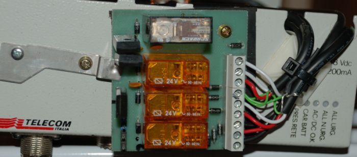
Antenna switching unit

Is the module hosting the antenna switching relais. I went for using common relays powered at 24Vac (by the way, I supply them in
CC with a lower voltage because it's simpler - be warned that in this configuration relais get warmer and so you need to find the
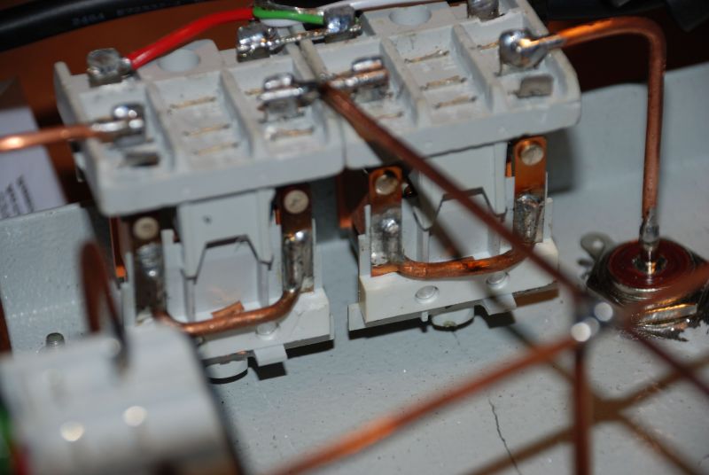
minimial voltage to use to avoid heating). Relais have been hacked removing cables to the central pole and connecting the two farest
thin laywers (photo explain better than words..): in other words, relay won't be used as a SPDT switch but will act like an old
"knife switch". Note that I found this solution surfing the net.
If you need, you can easly change relays and their configuration with one that fits better in your environment (i.e. vacuum relais
from Siemens) because the BCD converter supply an output for every relay.
I measured the loss of this switch using a simple method like measuring the power before and after the switches: i found about 0,5 dB
loss but I'm not sure of the test because I used commercial wattmeters and the antenna as load (currently, I don't have a dummy
load available). Just one note: in the photos you will see lines connecting relais and PL made by rigid copper wires. Later I
replaced them with coaxial cables to minimize losses (from 1,5 dB with just copper wiret to 0,5 dB using coaxial cables).
On the Net I've seen many other projects, some of them using a microstrip PCB and common relays: probably in the future I will reengineer
the relays part and use microstrip lines to maintain the impadance constant along the paths within the switch.
| <<< Summary <<< | >>> Usage >>> |