CI-V based remote antenna switch
Conections (rear panel)
Let's examine the rear panel with all required connections

On the left side, there is the pwer supply connector as well as the power on switch: as said earler, I used an external power supply since the unit can accept a wide range of voltages and generate appropriate voltages to drive external relays. Positive terminal is the central one (as in most devices) but the internal power supply employs a rectifier to manage polarity reverse.
The little switch between the power supply and the DB9 connector should be used when performing firmware updates
using the USB port on the right side: when moved on the "firmware upgrade" position, this switch disconnect the CIV from
Arduino; otherwise, if CIV is connected to the Arduino, update will fail during the last step (Arduino reboot).
To upgrade the program on Arduino, simply connect the USB port, move the switch on the proper position and perform the upgrade
using Arduino software from PC. When done, move the switch back to restart normal operation.
P.S.: I printed the firmware upgrade label too far from the switch, but I really don't have time (and need) to print again the panel!
The DB9 connector is used to control the remote unit: pin layout is quite simple since it uses only pins 1,3 and 5 (BCD bit
1, 2 and 3) while all other pins are grounded.
- PIN 1: BCD code bit 1
- PIN 3: BCD code bit 2
- PIN 5: BCD code bit 3
- Other pins: GND
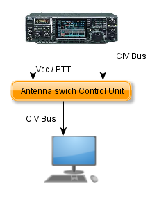
On the upper right side there are two CIV inputs which are connected together: one should be used as input from radio
and the other one can be used as an output towards the computer.
The device can operate in two different modes:
-
"Spying" the data flow between the radio and the computer (in this case you probably would use both CIV ports)

-
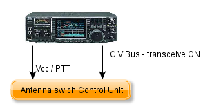
Waiting "CIV TRANSCEIVE" commands sent from radio at every change of frequency/mode (in this case only one CIV input will
be used - remember to turn on the "CIV TRANSCEIVE" option on rtx).

Finally, the Icom ACC2 connector is used to get the 12Vcc from radio as well as PTT signal (if you don't need opto-isolation
but you leave this module in place, you'll need to supply 12Vcc because otherwise the optoisolator won't work - as said eaarlier,
you can simple put the CIV signal directly into Arduino PIN0). I went for a 4 pin miniDIN connector because it was the only one
I found that can be soldered on PCB.
Pin layout I've used:
- PIN 4 (looking at the female connector, the upper right one): 12 Vcc power supplu
- PIN 3 (looking at the female connector, the upper left one): PTT Signale (grounded on TX)
- PIN 1 e 2 (looking at the female connector, the lower ones): GND
Front Panel
Let's have a look at the front panel

Let's start with the bigger part, i.e. the LCD module used to show all informations about the device:
- The upper left part, as you can easily understand, shows the operating frequency read using CIV from the radio.
- Immediatly in the left you can find the name for the current ham radio band (based on the frequency) or, in case you tune an out of band frequency, you will get a NotHam value.
- On the lower line, you can find the currently selected antenna number (near the Ant value)
- Finally there is the anenna name as configured within the device. If no antenna is selected (example: when you power on device but no CIV data has been received) you will get on the second line Ant 0: NoAntenna.
A quick note regarding both MSG key and led: the latter reports to the operator that there are messages about the device status that can be shown pressing the MSG key (to hide the message, press again the MSG key or simply wait some seconds). There are 5 different messages available:
- Manual mode enabled: control box is working in manual mode and so antenna switching must be done throu the UP and DWN keys (MSG led blinks).
- Frequency is not a valid HAM band: should be cleare! When configuring the box, you can link an antenna to each ham band. If the tuned frequency doesn't fall within an ham band limits (ex. when tuning a newly installed antenna or when BCLing or listening utilities on HF), the device won't switch the current antenna (it doesn't know the band thus cannot select an antenna).
- No Antenna for current band: displayed when you switch on a band where no antenna has been configured. (i.e. I don't have neither 160 or 6 meters antenna so when it happens to switch radio on those bands, I get that message).
- All antennas are disconnected: this message is normally displayed when starting the control box because no data has been yet received from the radio.
- No data received from radio: when the control box doesn't receive any CIV data from the radio for one hour, it displays this message to warn operator that there could be an issue with CIV communication between the radio and the device. It can also happens when using the device in TRANSCEIVE mode and stay on the same frequency for more than 1 hour as well as after an 1 hour you powered off the radio.
System usage should be quite simple: thour the frequency information from CIV data, the box decodes the ham band and switches the antenna based on configuration stored within the device. Automatic switching doesn't occur when:
- You move to a band where no antenna has been defined
- You move outside an ham band
- Device is working in manual mode
- Radio is in TX
Manual mode is enabled by simply pressing UP or DWN button (antenna is switched to next or previous one) and is disabled by pressing the ESC key. When in manual mode, the MSG led blinks to remmeber operator that switching won't automatically occur when changing band. When going back to auto mode, antenna is switched to the configured one for the band you're on.
| <<< Block Diagram <<< | >>> Configuration >>> |
